


Разное
-
На коммутаторах Cisco, если автосогласование было неуспешно, то режим дуплекса будет таким: если скорость 10 или 100 Мбит/с – half-duplex; если выше – full-duplex.
-
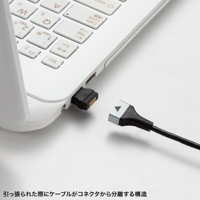
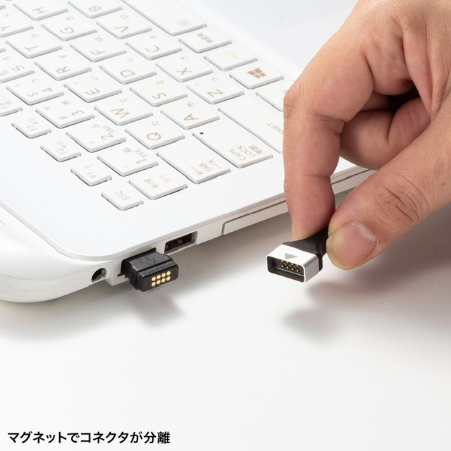
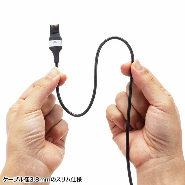
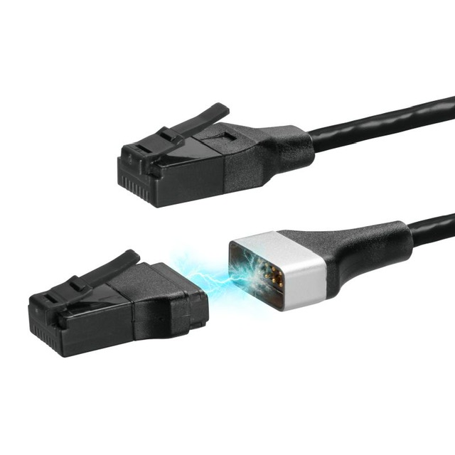
В Японии выпустили патч-корд с магнитным разъёмом, Новинку представил бренд Sanwa. Главной особенностью кабеля KB-SL6ABA (Cat. 6a), как можно понять из заголовка, стала разъёмная конструкция на магнитах, которая напоминает коннекторы MagSafe для ноутбуков Apple. Благодаря этому решению, если за патч-корд резко потянуть, то он просто разъединится, что защитит от поломки LAN-порт и ваше устройство. Стоимость метрового Sanwa KB-SL6ABA в Японии составит 27$, а 10-метровой — уже 42$. О появлении новинки в других регионах информации пока нет. 🔥Регард
- Про qos отдельно
- 100G Ethernet внутри реализован как объединение 10Gx10 или 25Gx4. Одну линию с нужной частотой (требуется 100 ГГц вместо 10х10 ГГц, а если быть точным 10.3125Ghz или 25х4 ГГц/25.78125Ghz) пока слишком сложно сделать.
- В 100G Ethernet line rate требуется меньше наносекунды (0.96 наносекунд) на обработку пакета (IFG/IPG; 96 нс для1G).
-
B unicast MAC-адресе первые 24 бита представляют собой OUI. Он необходим для идентификации производителя оборудования (вендора).
- Хорошая статья о трех основных форматах Ethernet Frame
- Ethernet II – наиболее часто встречаемый тип фрейма Ethernet,
- IEEE – with LLC:DSAP/SSAP,
- IEEE – with SNAP
In summary there are three different Ethernet frame types used. DIX frame, also called Ethernet II, IEEE 802.3 with LLC and IEEE 802.3 with SNAP encapsulation. There are others out there as well but these are the three major ones and the DIX one is by far the most common one.
DSAP/SSAP: SAP stands for Service Access Point, the S and D in SSAP and DSAP stands for source and destination. They have a similar function as the Ethertype.
From a vendor perspective this is good because then they can have an OUI and then create their own types to use. If we look at PVST+ BPDUs from a Cisco device we will see that they are SNAP encapsulated where the organization code is Cisco (0x00000c) and the PID is PVSTP+ (0x010b). CDP is also using SNAP and it has a PID of CDP (0x0200).
- Type Field Ethernet (EtherType TPID):
- 0x0800 – IPv4
- 0x0806 – ARP
- 0x8100 – 802.1Q tagged frame
- 0x86DD – IPv6
- 0x8847/8 – MPLS unicast/multicast
- 0x88A8 – Q-in-Q
- 0x88CC – LLDP
# tcpdump -e -i eth0
22:40:47.297489 00:0e:0c:9b:fa:ce (oui Unknown) > 00:13:d4:8b:c8:b6 (oui Unknown),
ethertype 802.1Q (0x8100), length 106: vlan 4, p 0, ethertype 802.1Q, vlan 8, p 0,
ethertype IPv4, 192.168.1.2 > 192.168.1.1: ICMP echo request, id 64531, seq 146, length 64
- Преамбула – последовательность сигналов, которая позволяет на принимающей стороне идентифицировать начало фрейма.
The preamble is a pattern of alternating ones and zeroes and ending with two ones. When this pattern is received it is known that anything that comes after this pattern is the actual frame.
- Дополнительные накладные расходы Ethernet (помимо header/footer), при расчете полосы они учитываются при расчете теор. предела PPS (если их не включать в расчет PPS теор. предела выше), относятся к L1:
– 12 byte IFG (Inter frame gap)
– 7 byte PRE (Preamble)
– 1 byte SFD (Start of frame delimiter)
- Почему минимальный размер 64 байта – ethernet header 18 byte + minimum payload 46 byte. Минимальное ограничение payload в 46 byte обусловлено “исторически так сложилось“. А конкретнее алгоритмом CSMA/CD – чтобы хост всегда успевал услышать о том, что произошла коллизия до того, как полностью передал фрейм. Хотя в сети возможно появление фреймов менее 64 байт – есть даже счетчик соответствующий на оборудовании (runts).
https://learningnetwork.cisco.com/thread/44208
FOR THE 802.3 FRAME CONTAINS

Ethernet Header = 18 Bytes [Dst Mac(6) + Src Mac(6) + Length (2) +CRC(4)]
Minimum Data Portion = 46 Bytes
Minimum Ethernet Frame Size = 64 Bytes

Frames must be at least 64 bytes long, not including the preamble, so, if the data field is shorter than 46 bytes, it must be compensated by the Pad field. The reason for specifying a minimum length lies with the collision-detect mechanism. In CSMA/CD a station must never be allowed to believe it has transmitted a frame successfully if that frame has, in fact, experienced a collision.

In the worst case it takes twice the maximum propagation delay across the network before a station can be sure that a transmission has been successful. If a station sends a really short frame, it may actually finish sending and release the Ether without realising that a collision has occurred.

Thats why it is/has a minimum of 64 Bytes.
-
Время передачи кадра по кабелю:
- 1518б передаётся
•	0.1 мс (чуть больше) по каналу 100мб,
•	0.1 мс по каналу 1000мб
•	0.01 мс по каналу 10GbE
- 9кб
•	1мс (почти) передается по каналу 100мб,
•	0.1 мс по каналу 1000мб
•	0.01 мс по каналу 10GbE®
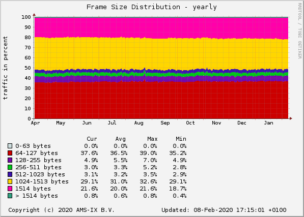
- Распределение по размеру фрейма у AMS-IX
- с 1514 byte frame size (видимо без CRC стандартные 1518) – 22%
- 1000 – 1513 byte frame size – 30%
- 64-127 byte frame size – 38%
Основной перечень стандартов 802.3 с кратким описанием.
Интересное:
- (wifi, ethernet) 2.5 и 5G ethernet часто используются для подключения Access Point (напр. 802.11AC) без необходимости перепрокладывания кабеля
- 2.5, 5G copper стандарты – IEEE 802.3bz (2.5 GBASE-Т и 5GBASE-Т). Причем для 2.5G достаточно четырехпарного Cat 5e.
- 25 и 40G copper стандарты используют кабель Cat 8 с длиной до 30 метров
- 100Base-T1, 1000Base-T1 – описаны в 802.3bw/802.3bp automative ethernet (Automative Ethernet Physical Layer).
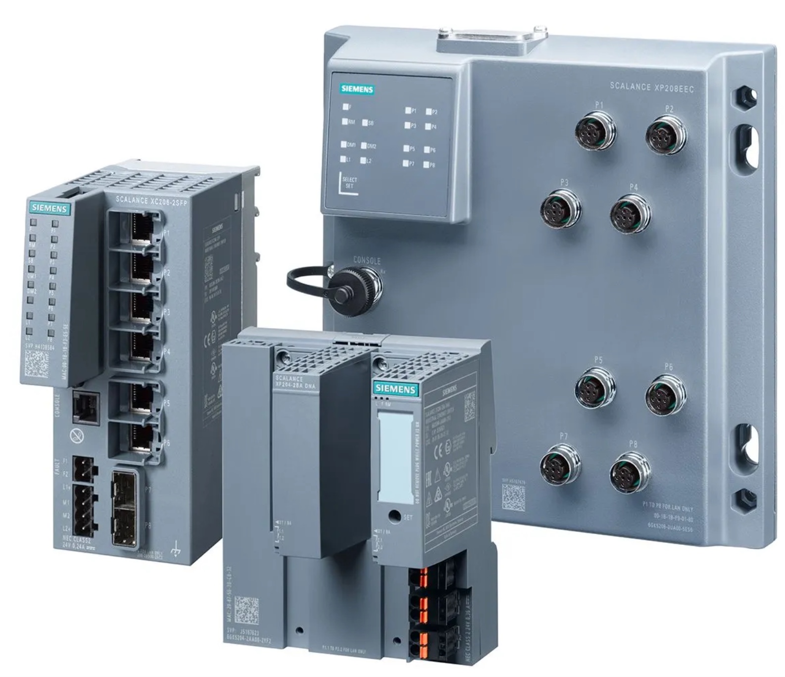
- (Sfp, ethernet) M12 – industrial ethernet разъем Ethernet, хотя в некоторых случаях даже Siemens использует RJ-45/RJ45, просто со специальными патч-кордами. Еще из интересных промышленных вендоров –
Westermo Network Technologies.
- L1 стандартов тестируется например с помощью осциллографа Keysight.
Прикольная табличка. Из нее следует, что максимальной скоростью для 5e медного кабеля является 2.5 gbps (2.5GBASE-T, 802.3bz). А в целом для RJ-45 меди (есть еще твинаксиальная медь) ограничение в 30м на скорости 40 gbps.
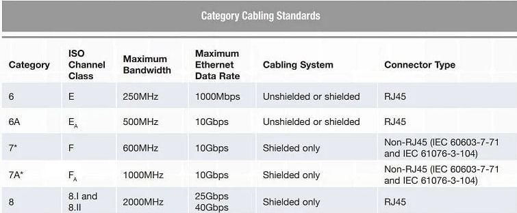
| Название | Скорость[10] (Мбит/с) |
Количество пар[11] | Бит/Гц | Спектральная ширина (МГц) |
Требуемый кабель[12] | Рейтинг кабеля (МГц) |
|---|---|---|---|---|---|---|
| 10BASE-T | 10 | 1 | 1 | 10 | Кат. 3 | 16 |
| 100BASE-TX | 100 | 1 | 3.2 | 31.25 | Кат. 5 | 100 |
| 1000BASE‑T | 1,000 | 4 | 4 | 62.5 | Кат. 5е | 100 |
| 2.5GBASE-T | 2,500 | 4 | 6.25 | 100 | Кат. 5е | 100 |
| 5GBASE-T | 5,000 | 4 | 6.25 | 200 | Кат. 6 | 250 |
| 10GBASE-T | 10,000 | 4 | 6.25 | 400 | Кат. 6А | 500 |
| 25/40GBASE-T | 25,000 – 40,000 | 4 | Кат. 8 | 2000 |
Выберите неверное утверждение, касательно полей “Преамбула” и “SFD” в заголовке Ethernet
1) Размер “Преамбулы” – 7 байт, а “SFD” – 1 байт
2) Каждый байт полей “Преамбулы” и “SFD” в двоичном представлении выглядит как 10101010
3) Оба поля находятся в начале заголовка Ethernet
4) Поля используются для синхронизации между устройствами отправителя и получателя
Ответ 2. "Преамбула" состоит из последовательностей 1 и O. "SFD" также, но за исключением последнего бита, который равен 1. Эта 1 сигнализирует о том, что следующим байтом будет поле МАС-адреса назначения.
режимы коммутации
- С промежуточным хранением (Store and Forward). Коммутатор читает всю информацию во фрейме, проверяет его на отсутствие ошибок, выбирает порт коммутации и после этого посылает в него фрейм.
- Сквозной (cut-through). Коммутатор считывает во фрейме только адрес назначения и сразу после выполняет коммутацию. Этот режим уменьшает задержки при передаче, но в нем нет метода обнаружения ошибок.
- Бесфрагментный (fragment-free). Этот режим является модификацией сквозного режима (принимаются 64б, первые 64 тк именно в них чаще всего происходит коллизия.). Передача осуществляется после фильтрации фрагментов коллизий.
MTU MISC
- При изменении MTU на интерфейсе в сторону уменьшения Linux автоматически начинает понижать MSS.
Real example
MTU 1500 - hostA MSS 1353
MTU 1500 - hostB MSS 1460
MTU 1400 - hostA MSS 1276
MTU 1400 - hostB MSS 1360
- Максимальный MTU 1500 по умолчанию так же как и минимальный размер 64 байта имеют объяснение в “исторически так сложилось“. Объясняют, что высокий MTU потенциально хорош в будущем, но на старте жизни Ethernet посчитали, что MTU выше 1500 может привести к увеличении стоимости производитва NIC и, как результат, меньшему распространению Ethernet.
In retrospect, a longer maximum might have been better, but if it increased the cost of NICs during the early days it may have prevented the widespread acceptance of Ethernet, so I’m not really concerned.
- IP MTU 9000 – используется в datacenter, пример Честный Знак
- Дропы из-за MTU могут быть и бывают, все о них знают, но не все понимают, почему это происходит:
- Фича:
- дропается фрейм чаще всего на входе простым превышением MTU
- Фича:
Ingress Packet Drops (Lower Ingress MTU)
If either of these counters increment it usually it means that the received packets have arrived above the configured MTU.
-
-
- но в теории может и на входе т.к. MTU исходящего интерфейса ниже чем фрейм, который через него пытается “пролезть”, а устройство не умеет или не хочет фрагментировать пакеты (напр. коммутатор)
-
MTU and Fragmentation
For IPv4, if an outgoing IP packet is larger than the specified MTU, it is fragmented into 2 or more frames. Fragments are reassembled at the destination (and sometimes at intermediate hops), and fragmentation can cause performance degradation.

For UDP or ICMP, the application should take the MTU into account to avoid fragmentation.

The Firepower Threat Defense device can receive frames larger than the configured MTU as long as there is room in memory.
-
- Баг: После изменения system mtu на Catalyst лучше перезагружаться – иначе на рандомных портах могут быть потери фреймов большого размера. При этом заданный mtu может быть однозначно достаточным, для того, чтобы фреймы прошли без отбрасывания. Напр. фиксировал такую проблему с catalyst 3850 с IOS-XE – при MTU 9000 не проходили tcp транзакции для ряда протоколов (при этом tcp коннекции устанавливались корректно), после установки MTU в 1500 и перезагрузки коммутатора – все ок.
Switch(config)# system mtu 1900
MTU PMTUD (Path MTU Discovery)
MSS is negotiated, but it might not indicate the actual MSS that can be used. This is because other network devices in the path between the source and the destination might have a lower MTU value than the source and destination. In this case, the device whose MTU is smaller than the packet will drop the packet. The device will send back an ICMP Fragmentation Needed (Type 3, Code 4) message that contains its MTU. This ICMP message allows the source host to reduce its Path MTU appropriately. The process is called Path MTU Discovery (PMTUD).
The PMTUD process is inefficient and affects network performance. When packets are sent that exceed a network path’s MTU, the packets need to be retransmitted with a lower MSS. If the sender doesn’t receive the ICMP Fragmentation Needed message, maybe because of a network firewall in the path (commonly referred to as a PMTUD blackhole), the sender doesn’t know it needs to lower the MSS and will continuously retransmit the packet. This is why we don’t recommend increasing the Azure VM MTU.
carrier-delay
Маленькие таймеры плохи тем, что могут вызывать доп. загрузку в случае короткого (на время холд) флапа соседа из-за флуда, скачка линка или еще чего. Примеры: сосед флапнулся, мы пересчитали все маршруты через него. Линк дернулся – мы изменили RIB соотетственно. Если сосед или линк поднимутся в ту же секунду, в которую упали – возможно, не стоит лишний раз пересчитывать RIB и прочее туда-сюда, используя некий умеренный порог (holdtime, carrier-delay) по срабатыванию триггера.
Carrier-Delay устанавливает задержку (holddown) реагирования системы на падение интерфейса.
- По умолчанию задержка выставляется маленькая (0,2 сек или 200 мсек по умолчанию).
- В общем случае значение Carrier-Delay должно быть меньше скорости двойного пересчета таблицы маршрутизации т.к. если оно больше – то сеть сошлась бы быстрее без carrier-delay, нежели с ним.
- Если линк часто флапается и роутер из-за постоянных пересчетов топологии/отправки trap/логгирования информации в системный лог и syslog начинает “тупить” – выставляем задержку побольше.
- Пример недостаточного значения carrier-delay (о carrier-delay в IT) + необходимости иметь механизм errdisable на flap порта – это когда D-Link DES-3028 при постоянных скачках линка коммутатор даже не успевает регистрировать события Down и в логах фиксируется постоянных Link UP. Коммутатор в таком случае может начать тупить и даже зависнуть по management после таких скачков. Лечится ребутом.
- Порт за флаппинг можно блокировать! Теоретически может приводить к деградации сервиса из-за того, что коммутатору приходится постоянно обрабатывать событие Up/Down: отсылать trap на SNMP-trap сервер о поднятии порта и появлении MAC (если успел), отсылать на порт loopback, писать данные в log и отправлять их в syslog.
carrier-delay [TIME] – sets the carrier delay time. If a link goes down and comes back up before the carrier delay timer expires, the down state is effectively filtered, and the rest of the software on the device is not aware that a link-down event occurred.
The default setting is 200 milliseconds. The value that you choose depends on the nature of the link outages and how long you expect these linkages to last in your network. In most environments, a lower carrier delay time is better than a higher one.
- Small carrier delay. When you set the carrier delay time to 0, the device detects each link-up/link-down event that occurs. Outages are detected sooner, and the IP route convergence begins and ends sooner.
- Large carrier delay. A large carrier delay timer results in fewer link-up/link-down events being detected. If your data links are subject to short outages (especially if those outages last less time than it takes for your IP routing to converge), you should set a long carrier delay value to prevent these short outages from causing unnecessary churn in your routing tables.
Router(config)# interface GigabitEthernet2/0/0
Router(config-if)# carrier-delay down msec 50
Router(config-if)# carrier-delay up 8
Ethernet OAm (802.3ah)
Протокол для мониторинга, обычно на практике используется на последней миле – позволяет как обнаружить ошибки (включая ошибки фреймов, unidirectional, dying gasp после shutdown/errdisable, etc), так и провести loopback тест (remote loopback), позволяющий зачастую продиагностировать/разграничить ЗО проблеиы, когда удаленная сторона делает по сути замыкание tx/rx. Поддерживается OAM только на p2p/full duplex линках, в качестве инкапсуляции в ethernet используется ethertype код протокола, аналогичного LACP (slow protocols) 8809 и аналогичный DST MAC.
https://ccnp-sp.gitbook.io/studyguide/l2vpn-and-ethernet/carrier-ethernet/802.3ah-ethernet-oam
Ethernet OAM is a protocol used for monitoring and troubleshooting Ethernet on a last-mile link.

Ethernet OAM was invented in order to use the same OAM tools that traditional WAN technologies like ATM and SONET had, for Ethernet. Ethernet was invented as a LAN protocol and did not originally have the same requirements that we impose on Ethernet today as a WAN technology.

You typically run Ethernet OAM on a point-to-point link between a PE and the demarcation device at the customer premises. The main features when using Ethernet OAM are: link monitoring (detecting errors and acting on them based on a threshold), remote link fault detection (notifying the peer of faults), and the ability to turn the remote partner into a loopback. We can easily lab Ethernet-OAM using CSR1000v.
Ethernet OAM is only supported on full duplex, point-to-point links. Ethernet OAM PDUs use the slow protocol destination MAC of 0180.c200.0002. You may recognize this because it is the same MAC that LACP uses! Slow protocols cannot exceed a maximum tramission of 10 frames per second. The idea behind “slow protocols” is that they have very low impact on overall bandwidth of the link. The ethertype for slow protocols is 8809. LACP is subtype 1 and Ethernet OAM is suptype 3.
Конфигураци в лабе на CSR1000v достаточно простая и похожа так же на LACP. Можно включать разные доп. фичи, напр. Loopback и errdisable при детекье определенных ошибок.
To configure Ethernet OAM you simply use the following command under the interface. I will also put CE1 in passive mode. By default it is in active mode. Active/passive mode works just like in LACP. The active side tries to initiate a session by actively sending OAMPDUs, and the passive side only sends PDUs in response. Two devices in passive mode will not become OAM peers.
#CE1
int Gi1
  ethernet oam
  ethernet oam mode passive
  ethernet oam remote-loopback supported
  ethernet oam remote-failure critical-event action error-disable-interface
#PE1
int Gi1
  ethernet oam
  ethernet oam remote-loopback supported
CE1(config-if)#ethernet oam mode ?
active Active mode
passive Passive mode
Запуск loopback.
ethernet oam remote-loopback start interface Gi1
Выводы show.
CE1#show ethernet oam discovery
GigabitEthernet1
Local client
------------
Administrative configurations:
Mode: passive
Unidirection: not supported
Link monitor: supported (on)
Remote loopback: not supported
MIB retrieval: not supported
Mtu size: 1500
Operational status:
Port status: operational
Loopback status: no loopback
PDU revision: 0

Remote client
-------------
MAC address: 5254.000f.d2cf
Vendor(oui): 00000C(cisco)
Administrative configurations:
PDU revision: 0
Mode: active
Unidirection: not supported
Link monitor: supported
Remote loopback: not supported
MIB retrieval: not supported
Mtu size: 1500


CE1#show ethernet oam status
GigabitEthernet1
General
-------
Admin state: enabled
Mode: passive
PDU max rate: 10 packets per second
PDU min rate: 1 packet per 1000 ms
Link timeout: 5000 ms
High threshold action: no action
Link fault action: no action
Dying gasp action: no action
Critical event action: no action
Link Monitoring
---------------
Status: supported (on)
Symbol Period Error
Window: 100 x 1048576 symbols
Low threshold: 1 error symbol(s)
High threshold: none

Frame Error
Window: 10 x 100 milliseconds
Low threshold: 1 error frame(s)
High threshold: none

Frame Period Error
Window: 1000 x 10000 frames
Low threshold: 1 error frame(s)
High threshold: none

Frame Seconds Error
Window: 100 x 100 milliseconds
Low threshold: 1 error second(s)
High threshold: none

Receive-Frame CRC Error
Window: 10 x 100 milliseconds
Low threshold: 10 error frame(s)
High threshold: none
Transmit-Frame CRC Error: Not Supported
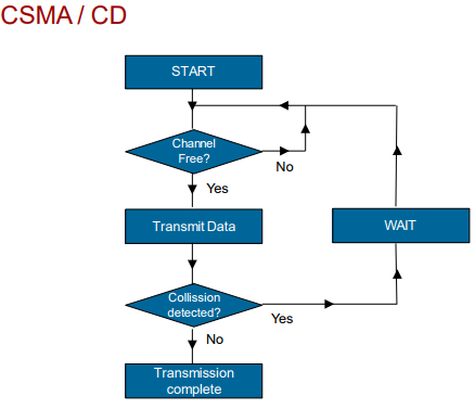
CSMA/CD
– (дублируется в вопросах/ethernet/wifi) Что такое коллизия? В каких сетях бывает? Какие методы борьбы существуют?
Искажение двух сигналов в следствии их “столкновения” (jam). Обнаружение коллизии в сетях Ethernet по алгоритму CSMA/CD (detection). Избежание коллизий по алгоритму CSMA/CA (avoidance).
В интернет, книгах, экзаменах до сих пор очень много информации про CSMA/CD. По факту в нормальных (дуплексных) сетях алгоритм давно не нужен, а начиная с <<1G/10G>> вообще выпилен из Ethernet для скоростного развития стандарта – по сути подход аналогичный параллельным интерфейсам, который сменили последовательные.
Весь смысл в том, что передавать в разделяемой среде в один момент может только один участник, иначе электрические сигналы будут накладываться друг на друга и кадры будут портится. Алгоритм состоял в том, что все передатчики должны убедится в отсутствии эл. сигналов (carrier sense) в разделяемой среде и только после этого осуществлять передачу. При обнаружении того, что среда занята, передатчик должен ждать рандомный период до повторной проверки среды. В случае обнаружения коллизии (наложения кадров) нужно прекратить передачу и опять ждать рандомное время (все равноправны).
Mac address
-
МАС-адрес источника всегда должен быть ((но не обязан :))) unicast. МАС-адрес назначения может быть unicast, multicast или broadcast.
- Восьмой (с начала) бит первого байта МАС адреса называется Unicast/Multicast битом и определяет, какого типа кадр (фрейм) передается с этим адресом, обычный (0) или широковещательный (1) (мультикаст или броадкаст). Для обычного, unicast взаимодействия сетевого адаптера, этот бит выставлен в «0» во всех пакетах, им отправляемых.
- Седьмой (с начала) бит первого байта МАС адреса называется U/L (Universal/Local) битом и определяет, является ли адрес глобально уникальным (0), или локально уникальным (1). По умолчанию, все «прошитые изготовителем» адреса глобально уникальны, поэтому подавляющее число собранных МАС адресов содержат седьмой бит выставленным в «0». В таблице присвоенных идентификаторов OUI только порядка 130 записей имеет U/L бит «1», и по всей видимости это блоки МАС адресов для специальных нужд.
mac address randomization (ios, android)
- persistent randomization – рандомизированный MAC генерируется обычно один раз исходя из анонсируемых AP параметров (SSID, security type) и в итоге даже удаление сети не приводят к сбросу этого MAC.
- Non-persistent randomization – рандомизация происходит каждый раз при подключении к сети, по умолчанию не используется
- При рандомизации используется локально значимое значение 7-го бита MAC адреса.
Persistent randomization
Android uses the persistent randomization type by default when the MAC randomization feature is enabled. Android generates a persistent randomized MAC address based on the parameters of the network profile including SSID, security type, or FQDN (for Passpoint networks). This MAC address remains the same until factory reset. The MAC address does not get re-randomized if the user forgets and re-adds the Wi-Fi network since the MAC addressed depends on the parameters of the network profile.
Persistent MAC addresses are necessary in cases where networks rely on the persistence of the MAC address to provide useful functionality to the user, for example, to remember a device and allow users to bypass the login screen as expected, or to enable parental controls.
For Android 10 and 11, the framework uses persistent randomization for all networks when MAC randomization is enabled.
Non-persistent randomization
Under the non-persistent randomization type, which is used for some networks in Android 12 or higher, the Wi-Fi module re-randomizes the MAC address at the start of every connection or the framework uses the existing randomized MAC address to connect to the network
Вопросы
IEEE 802.3 is a collection of standards that describe many generations of Ethernet versions (T/F).
T